3D Printed Model Rocket
- Dat Ha
- Aug 4, 2020
- 7 min read
Updated: Sep 1, 2020

Abstract
The purpose of this project was to explore and gain experience in the process of designing and manufacturing a model rocket at a low cost. 3D printing will be used to manufacture the components of the vehicle. Commercial Estes motors are used for safety and legal reasons.
Tools used
OpenRocket is used to make the initial design of the rocket. The final Computer Assisted Design (CAD) model of the rocket is done in Autodesk Inventor. The rocket will be 3D printed on a Prusa Mendel I3 that was bought used and the files will be sliced using PrusaSlicer.
Version I
Rockets of this version are named Flyer because they are intended goal is to test the flight handling of a 3D printed model rocket.
Version 1.01 - Flyer I
For the first attempt, the design chosen was a slim and tall rocket. Its interior diameter was 18 mm (same as the Estes A8-3 motor).
The rocket was printed in 3 parts: the nose cone, the body tube, and the lower body tube which has the fins attached to it. Launch lugs are printed a part of the body tube as well as the lower part.
The nose cone was made to sit inside the body tube and was printed with a slight angle between where it is smaller to fit into the body tube and its outside surface. This was the case to make it possible to print without support but caused a bigger than desirable gap between the nose cone and the body tube.

This version had a major issue. In attempt to make a lighter rocket with less drag, the fins were made too small. This caused instability during flight, which leads to the rocket flying at an angle and caused the nose cone to be freed prematurely. This led to the rocket not achieving a high altitude and falling shortly after the powered portion of the flight. (CHECK VIDEO TO BE SURE)
The chosen recovery system was a streamer since the body tube was too narrow for a parachute. Due to another design issue, the body tube was further narrowed by an anchor point for the shock cord. This caused the streamer not to be deployed.
The lower section of the rocket and the main body tube were not glued strongly enough, and the streamer and shock cord were packed in too tight. This led to the lower section and the body tube to be separated from each other.
As a final detail, the components were made to be 3 perimeters thick. This was strong and sturdy.
Version 1.02 - Flyer II

This version uses the same nose cone and body tube as version 1.01. The only part that changed is the lower part of the body tube which includes the fins. The major upgrade to this part was an increase in the fin dimensions to increase stability. It can be said that this upgrade worked since the rocket went up relatively straight and achieved a much higher altitude than the previous version.

Another upgrade from the previous version is the usage of only 2 perimeters of thickness on the walls and fins of the rocket. Due to a little under-extrusion on the printer used, there were some gaps on the fins. The gap is small and does not seem to affect the flight much. This also confirmed that 2 perimeters are enough to make a structurally stable vehicle.
Since only 2 perimeters were used while keeping the same external diameter was kept, the motor is a little loose. This caused the motor to be ejected from the rocket at some point during flights.
Due to the previously explained problem with the design of the rocket and the recovery system, no recovery system was installed on the rocket to save weight.
Version II
Rockets of this version are named Sightseer because their mission is to collect data in flight and to see how the computer, sensors and software handle being launched on a model rocket.
Version 2.01 - Sightseer I

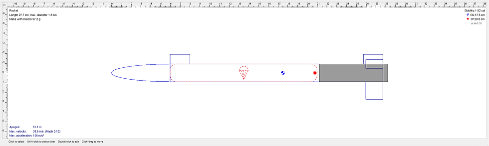
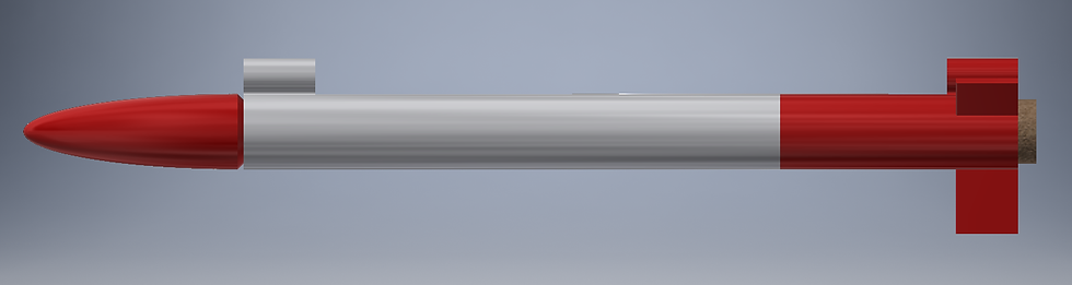
This version is a complete redesign of the rocket. The diameter was made wider in order for a parachute to fit. The previous version of the rocket used the friction of the fuselage skin of the
rocket to hold the motor. Making the rocket wider thus causes a need to have a motor mount.

The motor mount would need to hold the motor in place during the whole flight, center the motor in the fuselage, as well keep the ejection charge’s gases in the body tube in order for the gases to push the parachute and nose cone out of the body tube.

The nose cone will now sit outside of the body tube. This is meant to make installation of the nose cone easier since if the parachute fits tightly inside the body, the parachute does not need to be moved to allow space for the nose cone. This comes with a disadvantage that the top of the body tube will be narrower, but this was an accepted compromise.
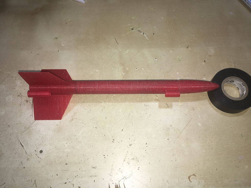
The whole rocket is now only 2 perimeters thick. The same issues that are present in version 1.02, regarding gaps in the fins, were also present, but once again, are negligible.

The body tube and the lower section are connected via a connecting right that also serves as the top and primary motor mount. This motor mount will push against an angled flange in the body tube. The flange and the top of the motor mount are angled to make the body tube printable without supports. The motor mount was also designed to keep the ejection charge’s gases in the body tube. The motor mount also needed to transfer the motors thrust to the rest of the rocket.
At the bottom of the lower section, there was also a centering piece for the motor. This piece could have been integrated into the lower section, but after the launch, there were scorch marks present on that piece, which indicates that the piece could fail easily. Therefore, the decision of making it a separable piece that was glued but is still removable with force, was the right choice to make.

During the print of the body tube, the body tube piece separated from the bed. This incident occurred when the printed started to print the connecting piece to the nose cone. The failure happened at the top of the print. In order not to waste the piece, an adapter that fulfills the role of the feature that was not printed on the nose cone was printed and glued into the body tube. The body tube had to be cleaned with a file to remove the beginning of the connector section of the body tube piece. There are still defects on the body tube piece, but in the bigger picture, are negligible.
As the design stage was coming to an end, it was decided that an optional Flight Data Recorder (FDR) should also fit into the rocket. This was not heavily taken into consideration as the largest component would have fit into the rocket’s diameter, and it was decided that the task of fitting the FDR in could be left after the rocket’s production. Since the mass of the FDR was not taken into consideration in the design, with the FDR, the rocket would be “over-stable.”
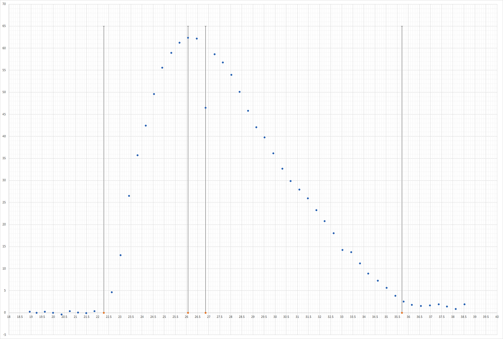
The FDR will use an Arduino to read the altitude from a MPL3115A2 altimeter and record it onto a micro SD card. It would run off a 3.7V Li-Po battery that was at our disposal. The FDR managed to fit snugly in the nose cone, but this led to some small issues in the data ready of the altimeter if there was pressure on the altimeter by the other components or the nose cone. There was also a bad reading on the altimeter when the ejection charged occurred. Our hypothesis is that this is caused by an increase in pressure in the rocket body, which caused an increase in the pressure reading and therefore a decreased in the altimeter’s calculated altitude. In the end, due to the pre-launch activities taking longer than expected due to some operators’ mistakes, the altitude did zero out before the launch.
Note that the rocket was manipulated after an igniter failure. The nose cone fell off when the rocket was tilted, and these actions could have compounded to the altimeter zeroing out correctly.
The graph below shows the recorded data. The four lines represent respectively the moment of lift-off, apogee, the moment the ejection charge is ignited, and the landing. This data was cleaned to remove points where the recorded altitude was the same, due to the low refresh rate of the altimeter. Many points before lift-off were also removed. The time was synced with the video with the ejection charge ignition as a reference.
The parachute was made using an old plastic bag that was given out at a fast food chain. All the cords used that is the parachute’s cords and the shock cord was made from an unknown string that was at our disposal. It was packed unconventionally due to the fact that duct tape was used to tape the corner of the parachute which made it harder to fit in properly using mode “conventional” methods of packing the parachute.
The launch lugs on the body tube also had a chamfer that made it possible to print without supports. This worked well without causing any noticeable side effects.
Apart from igniter issues, the launch went better than what we expected. The rocket went up straight and the parachute deployed fully. The FDR did record data throughout the flight, and it was successfully recovered and analyzed. The rocket motor stayed in the vehicle and the vehicle was still intact. As mentioned previously, scorch marks were present on the bottom centering ring. Dark color was also visible on the small gaps of the body tube. No wadding was used but the cord seemed to not have too much damage. It is a little stiffer than before and has darker spots, but there is no burned section on the cord.
Since with the motor, the rocket weighed more than the maximum lift-off weight of the Estes A8-3, an Estes B6-4 was used for the launch.
Version 2.02 - Sightseer II
Sightseer II is a slightly modified version of Sightseer I. The main difference is an additional electronics bay that is added between the top of the body tube and the nose cone. Since Sightseer I was designed with a high static margin for stable flight even without a payload, the additional bay and payload would increase the static margin beyond the desired maximum static margin value. To remedy the issue, 3 small fins were added on the additional bay.
The bay allows a gyroscope to be mounted vertically inside the rocket. With the gyroscope, the rocket orientation could be determined. During Sightseer II’s first launch, the software was not optimized, and the vibrations completely fouled the gyroscope values.
Nonetheless, Sightseer’s flight path was very close to vertical, confirming once again that the design of the vehicle was good. Despite a good ascend phase, the parachute did not deploy. In hindsight, we believe that the parachute was not properly folded.
Conclusion
Both Flyer and Sightseer have been very useful as a method to experimentally test out both the hardware and software. All experience learned from building these two rockets will be used to make Destiny, a rocket with active aerodynamic stabilization.


![Water Cooled 3D Printed PLA Component [Journal]](https://static.wixstatic.com/media/5130a3_ee2be7abbefd4c14b722d431d4ec98ad~mv2.png/v1/fill/w_980,h_577,al_c,q_90,usm_0.66_1.00_0.01,enc_avif,quality_auto/5130a3_ee2be7abbefd4c14b722d431d4ec98ad~mv2.png)
Comments